Delta – Frame Design
Design of Frame – Build diameter, horizontal extrusions length, diagonal rod length calculation.
The frame design depends mainly on build diameter.
Based on that value, horizontal extrusions is determined taking into account how big is your effector plate, how tall is your linear carriage from the plane of your tower and what is your desired offset from the belts when your effector is close to the tower.
I am attaching my handwritten calculation notes as images. It is based on simple trigonometric calculations. I hope it is self-explanatory. If it is not clear, let me know in the comments. I will try to clarify it.
I measured the outline of triangular extrusions that will be used for vertical towers and sketched it in onshape. I will be using these values for further calculations in this post. Here is the sketch:

If you look from top, the extrusions along with build plate will be arranged as shown below:

The picture on the right shows the top view of the delta printer with corresponding distances. 15 mm is the width of truncated flat portion of the triangle. If the edges are extended, it will form a small equilateral triangle of 15mm side. The height of this small imaginary triangle from the imaginary tip is 13mm. This imaginary tip is where the horizontal extrusions will meet if extended to form 60 degrees angle. The height of triangular extrusions is 47mm from the base of the triangle to the flat truncated portion. For clarity, please refer to the original sketch and the handwritten note below.
The hypotenuse is the length of the line from the imaginary tip of the triangle to the centroid of the triangle (where all the altitudes meet). This centroid will be the centre of the build plate. The tower plane (base), i.e one of the faces of the triangular extrusion is 60mm (13mm from the imaginary tip of small triangle plus 47mm, the height of the extrusion) from the imaginary tip of the equilateral triangle. Look at the hand drawn figure.

My linear carriages are 24mm total height (including rails) from the tower plane. The belts are 6mm height (my printed carriage adapter thickness for holding the arms are 6mm from the linear carriages). I assumed an effector offset of 40mm. I added a 10 mm clearance so the effector does not hit the belt.
If you subtract the values of tower plane offset, carriage offset, effector offset and your allowance for clearance from your hypotenuse you will get the build radius. I wanted a build radius of 150mm radius. This value gives me an approximate hypotenuse of 290mm. Based on these value and the geometry of the equilateral triangle formed by horizontal and vertical extrusions, I get a horizontal extrusion length of 474mm.

As a sanity check, I used a build radius of 145mm (290mm diameter Kapton heater) that should lie within the horizontal extrusion for insulation purposes. I used this radius value to calculate the length of horizontal extrusion.

Horizontal extrusion length is preliminarily chosen as 480mm. The reason it is preliminary is because of the diagonal arm length. They need to be taken into account while deciding extrusion length.
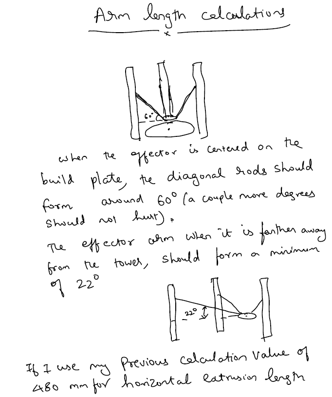
The diagonal arm length is based on two rules:
Rule 1: The diagonal arm should form 60 degrees with the horizontal plane when the effector is centred
Rule 2: When the diagonal arm is farther from its tower (when the effector is at the edge of build radius), it should form at least 22 degrees with the horizontal
If our horizontal extrusion length and chosen diagonal arm length satisfies these two criteria then we are fine.


Based on my notes and calculations, I decided on 480mm long extrusions and 360 mm long diagonal arms.
Hope you could follow my rationale for the frame design for my delta. If you find any mistakes, please feel free to leave a comment. If you need some clarification, please comment or contact me.
I plan to use 350mm diameter aluminium tooling plate within the triangle base. Just to check the interference, I made a quick 3D model of horizontal and vertical extrusions and build plate in onshape and assembled them. Here is the link to the file:
In the next post, I will talk about the frame assembly.

Hello.
I planing make delta printer. Your vertical profiles is very easy to mount frame. What kind of vertical profiles you use? Please send me link or something info about.
LikeLike
I want to make 200×200 square and 250mm build volume. What sizes of profiles i must use?
LikeLike
Hi Marcin,
Here is the link for the extrusion:
http://www.smt-montagetechnik.de/produkte/1120n.htm
I think I have described the calculations in the blog post. Anyways, If I were you, I will keep the horizontal extrusions same (480mm) because if you use bigger effector or some cooling fan setup it might eat your printing area. I have such setup and my print volume is 200mmx200mm square. I can safely print 400mm high objects without any problem, so reduce 150mm in the vertical extrusions.
In short, get 480mm horizontal extrusions of size 40×40
1 metre of vertical extrusions of size 40×40
Best Regards,
Vasan
LikeLike