
Delta – Frame Assembly
I have decided on 480mm length based on calculations in the previous post. I used 4040 cross section for top horizontal extrusions and 4080 cross section for bottom horizontal extrusions. The extrusions have 9mm through holes drilled for M8 bolts and 16mm holes for the bolt head to seat on extrusions. The onshape cad file for both 4040 and 4080 extrusions with drilled holes are here:
Here is the picture of 4040 extrusions with holes drilled:
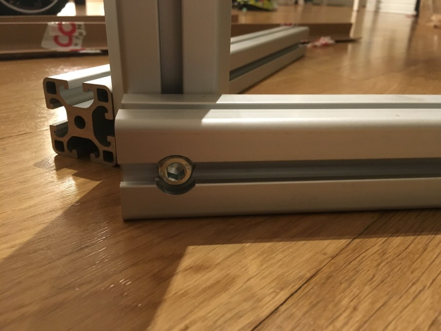
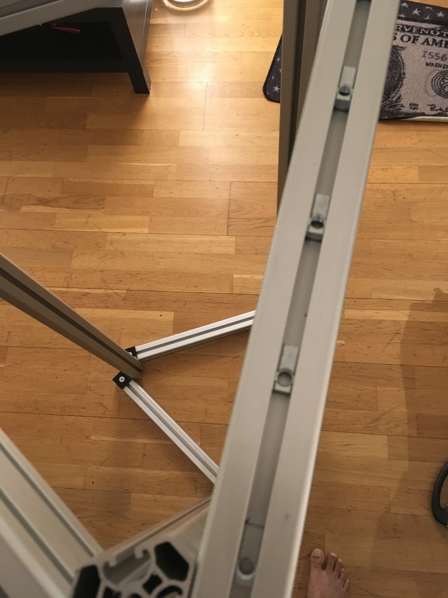
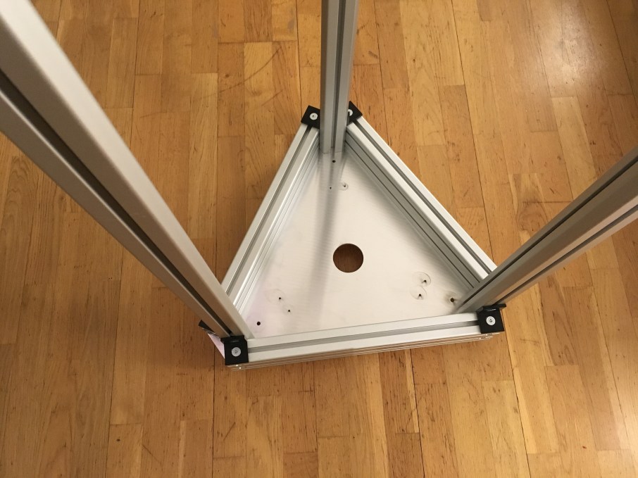
The horizontal extrusions are placed on the sides of vertical triangular extrusions as below:


Using M8 bolts and spring loaded t nuts fasten the horizontal extrusions snugly with triangular extrusions but not too tight to form the frame. Please ensure the horizontal frame is flush with vertical extrusions both on top and bottom using a spirit level.
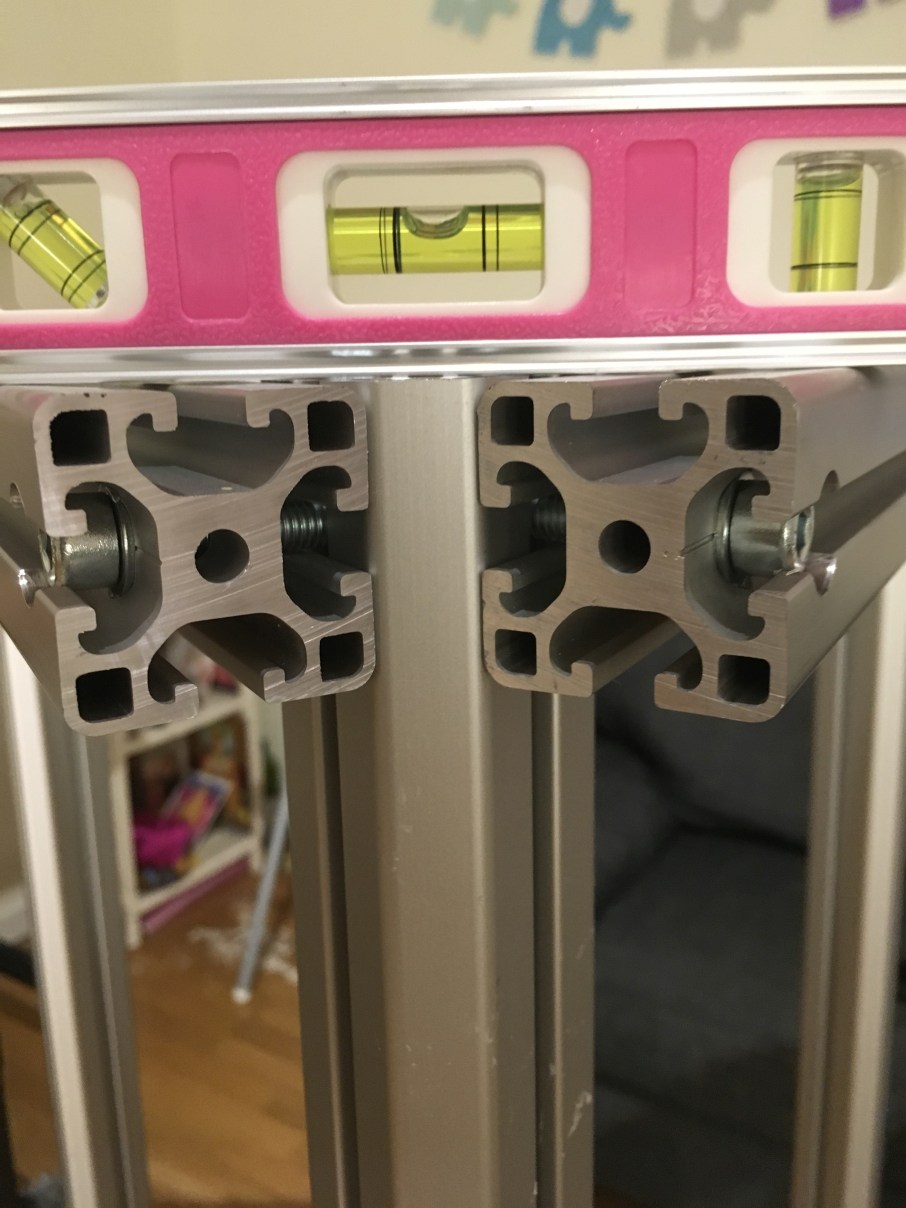
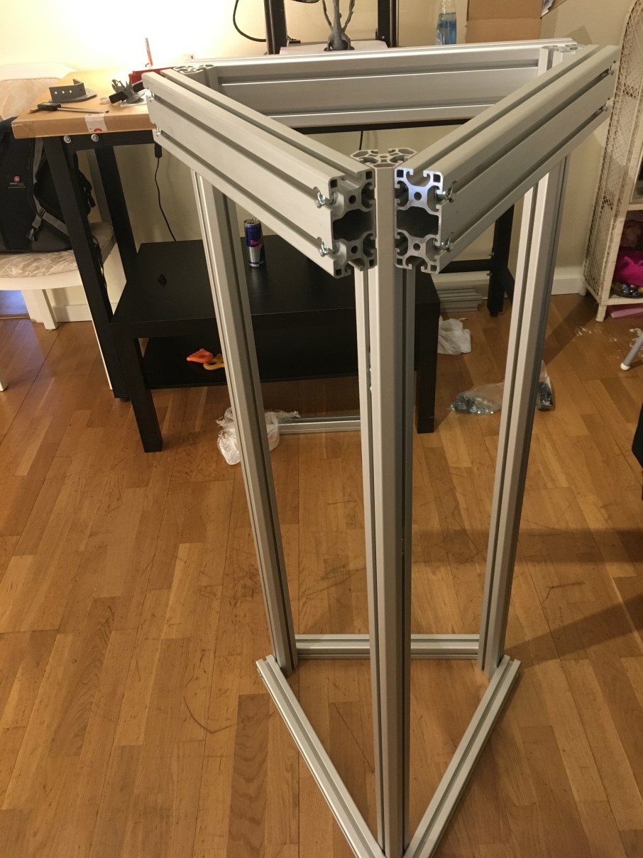
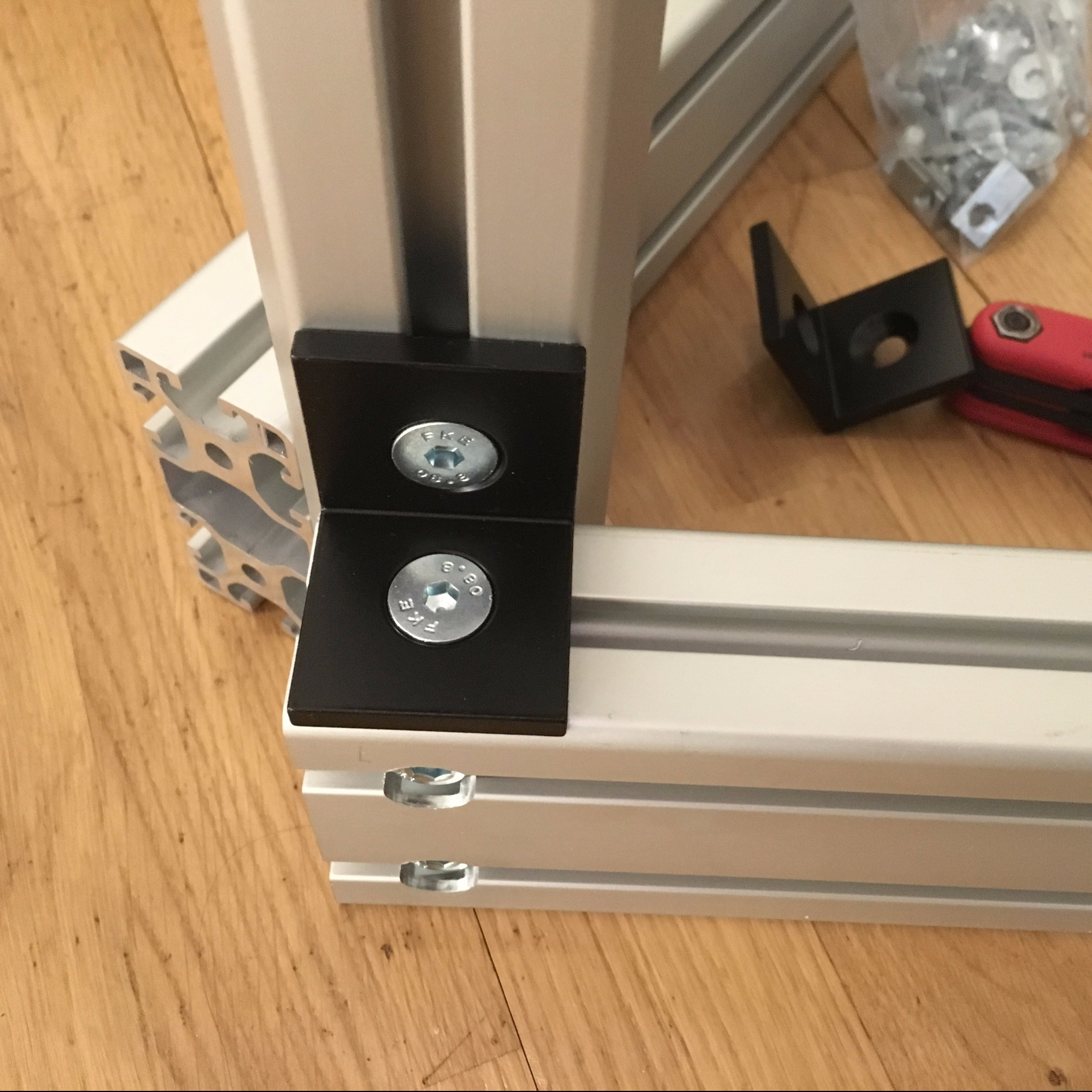
I used 90-degree angle bracket (black) at the corners both at top and bottom to make sure the horizontal and vertical extrusions are perpendicular to each other.

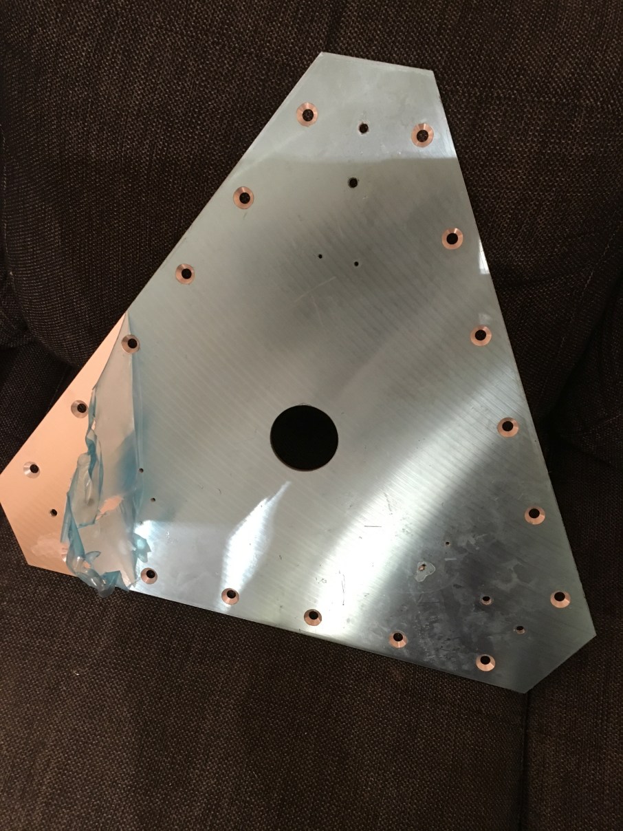
To ensure the horizontal frame is flush with vertical extrusions and have the same tower spacing (distance from the vertical tower to the horizontal extrusion) at top and bottom, I used a 5mm flat tooling plate cut to the dimensions of the equilateral triangle formed by the horizontal extrusions.
They have M8 countersunk holes along the edges of the triangle to attach the horizontal extrusions and one hole at each of the vertices to attach the vertical extrusions. I can attach adjustable feet at the vertices to raise the printer for easy access to wires.I have a 60mm diameter hole at the centroid of this triangular plate to route the wires from motors and heated bed.
There are three pairs of holes on the plate close to the tower for mounting stepper motors. I used 4080 for bottom extrusions because I need some clearance between stepper motors and Kapton heaters. Moreover, it gives a very solid base.
I made two of these plates, one each for top and bottom. Using spring-loaded t-nuts and M8 bolts the plate is attached to the extrusions.
Here is the onshape link for the sketch:
Picture of the plate and how it is attached to the extrusions
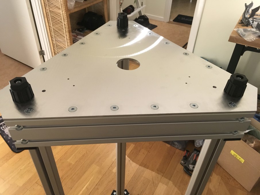
Once you have everything in place, use two verniers to check the tower spacing both at the top and bottom. Once you are satisfied with the flatness and tower spacing do the final tightening and check again. Build your frame as precise as possible. It will help you to calibrate the printer easily.
Here are the links for the parts purchased from dold-mechatronik for assembling the frame:
Aluminium Extrusions:
https://www.dold-mechatronik.de/navi.php?a=36839&lang=eng
https://www.dold-mechatronik.de/navi.php?a=36837&lang=eng
90-degree angle bracket kit:
https://www.dold-mechatronik.de/navi.php?a=5257&lang=eng
M8 Spring loaded T-nuts:
https://www.dold-mechatronik.de/navi.php?a=27873&lang=eng
Adjustable foot:
https://www.dold-mechatronik.de/navi.php?a=5232&lang=eng
I sourced the 5mm tooling plate from one of the local workshops and machined it there.
I might have been over cautious in building the frame but I want to be safe than sorry at later stages of printer calibration. In the next post, I will write about mounting the motion systems (linear rails and motor) and others.
