
Delta – Motion Systems
In this post, I will be writing about assembling linear rails, carriage block, effector, stepper motors, electronics control board (Duet Wifi) and board mount.
I used linear rails instead of wheel carriages. The jury is still out on which yields better results. I prefer linear rails because they are precise (assuming you have a good quality one) and used in many other precision machines (CNC and alike). I believe it is easier to have good lubrication between linear rails and carriage block than between wheels on v-slots. Moreover, for my triangular extrusion, it takes a bit more effort to make the motion systems with wheels. Instead of buying from aliexpress, I got the linear rails and carriage blocks from Germany (link below) but the company which provides them is from Taiwan and it is called Chieftek Precision Company (CPC). It is a bit more expensive.
Linear Rails:
Linear Rail Carriages:
M4 Bolts for fastening the linear rails with triangular vertical extrusions:
Springloaded M4 T nuts:
As a cheaper and smarter alternative, I would suggest getting MGN12 or 15 rails and corresponding carriage blocks from robotdigg. Take the steel balls from the blocks, replace them with good quality ones, bathe them in lithium grease, pack them again into the blocks. Make sure you get stainless steel rails to avoid corrosion. Also, lubricate them with 68 Cst viscosity oil or very close to it. 100Cst also works fine. It will help you to have a smooth and precise motion. This option will save you money.
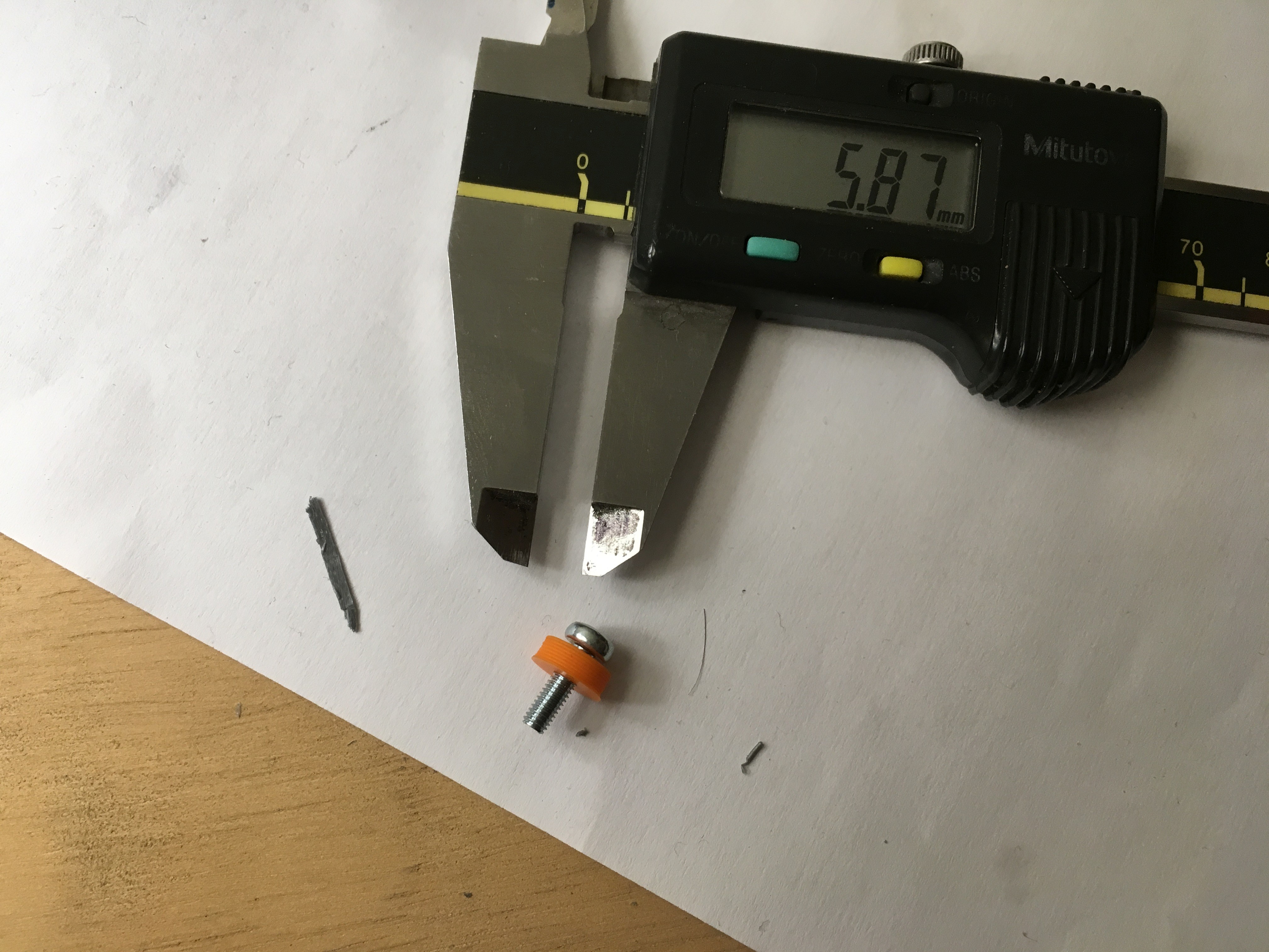
For mounting end stops at the same height from the top, I used a 120mm spacer. The spacer is butt against the 90 degree bracket. The spacer is fixed to vertical extrusion with a small screw and t nut.

Here is the CAD file for the spacer.
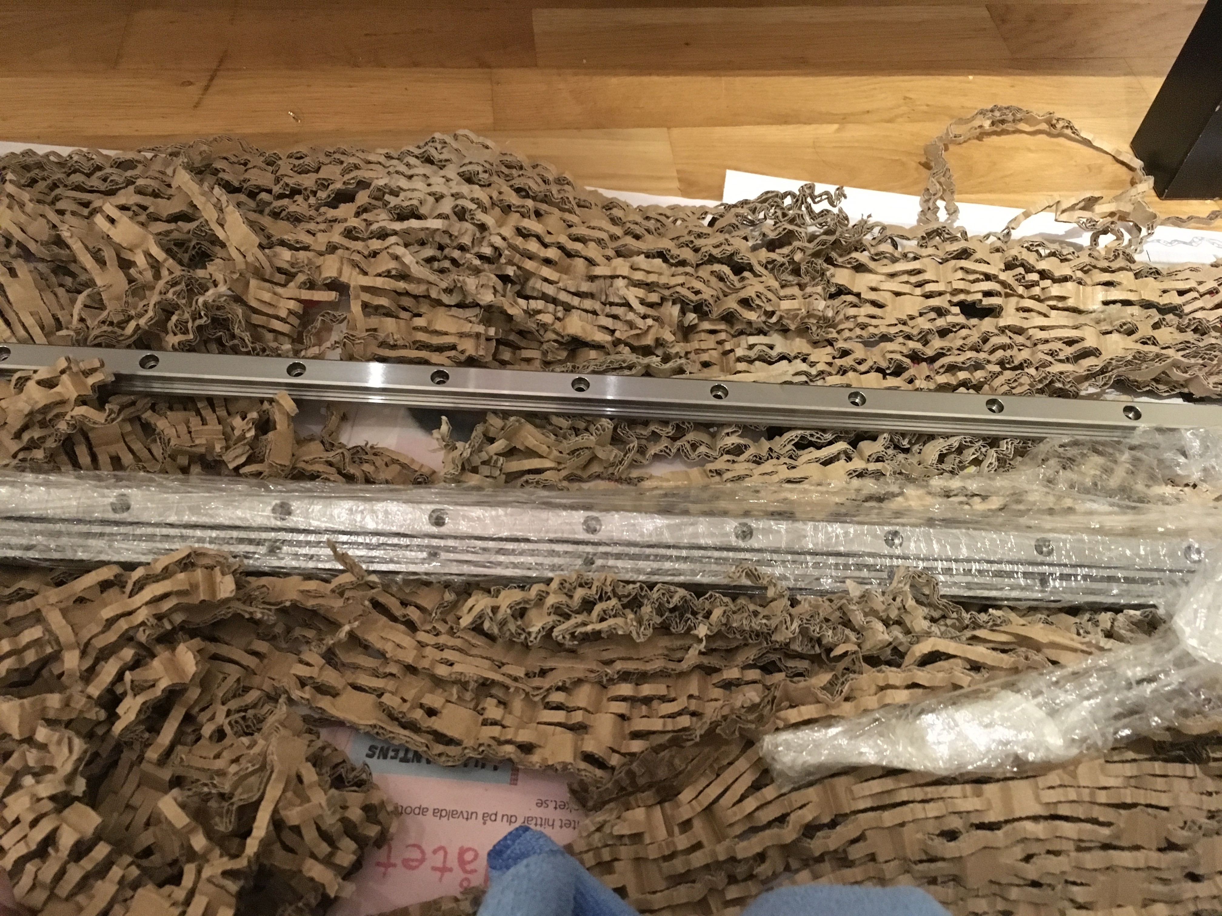
Spring loaded M4 T-nuts were placed in the extrusion slots for fixing the linear rails. Before using the rails, please clean the oil on the rails with a micro fibre cloth, then clean with a solvent. The linear rails were butted against the spacer. M4 screws were placed in the 60mm pitch holes of the linear rail. The other end of the screws thread into the T nuts for securing them with vertical extrusions. At the bottom of the linear rails, I used a small stopper so that the linear carriage blocks do not slide off the rails during assembly. Once the rail is fixed, now you can lubricate with 68Cst or 100Cst oil. I also fixed the motor mounts in the bottom plate. Please measure the distance from the face of the vertical extrusion to the vertical face of the motor mount. It is important to place them at a correct distance otherwise the belts will not be parallel introducing errors.
I also fixed the motor mounts in the bottom plate. Please measure the distance from the face of the vertical extrusion to the vertical face of the motor mount. It is important to place them at a correct distance otherwise the belts will not be parallel introducing errors.


Here is the CAD file for the Linear rail lower stopper.
I bought 0.9 degrees NEMA 17 stepper motor mount from OMC stepper online, here is the link:
Using 0.9 degree steppers can reduce or eliminate vertical fine artifacts (VFA) known as moire pattern in your prints. Duet3D documentation has a nice article on how to choose your stepper motor
For attaching the motor to the mount, I did not have smaller screws on that day. I was a bit impatient so I printed some spacers to fix the stepper to the mount. I used GT2 20 teeth pulley on the stepper motor shaft and 2mm pitch belt.

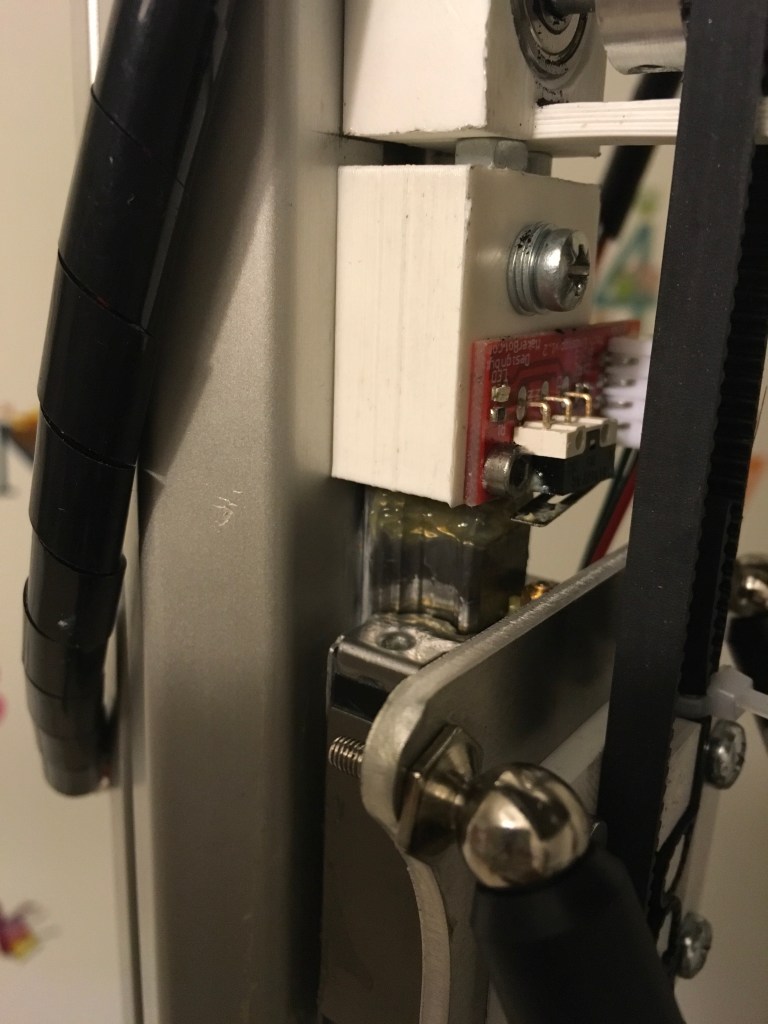
At the top end of the linear rail, I placed the end stop holder which butts against the linear rail and fix it with M4 screw and T nut.
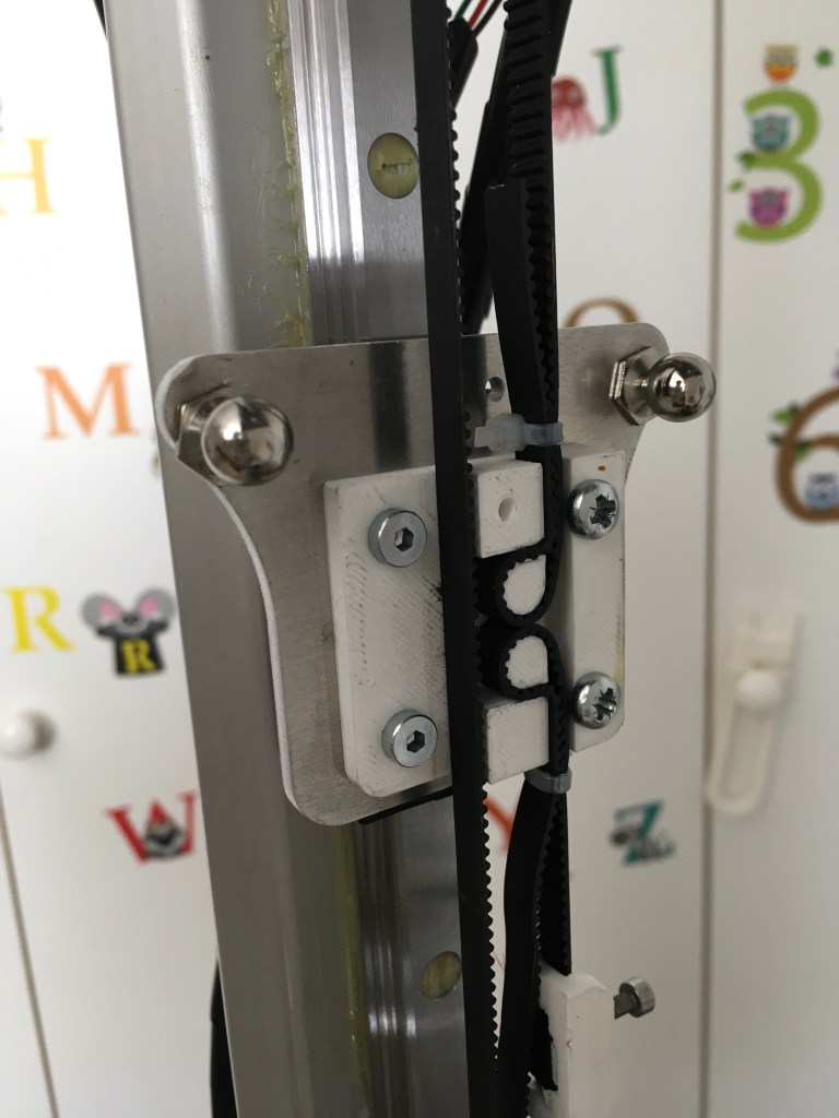
I suspected some tilt in the carriage and it might be due to the printed magnetic arm holder (the printed part which attaches to the carriage), so I changed it to aluminium. Here is the .dxf file for it, you can use it to either water jet cutting/laser cutting. The effector looks like the below picture.
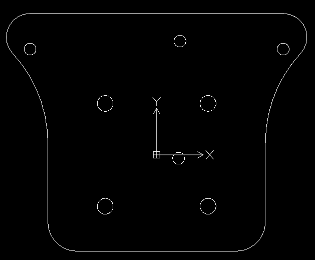
I used the above .dxf file to laser cut 3mm aluminium plate and mounted it on top of the linear rail carriage block. The four holes (forming a square) is of 4mm and 26mm spacing. You can fix a belt holder on top of it. You can see the linear rail below the end stop mount, carriage block and the laser cut aluminium carriage plate on top of it.
The spacing between screws to mount the belt holder is 26mm, which goes through the four holes of the carriage plate and there are 4 tapped holes on linear carriage block which exactly align with the carriage plate. Here is the link for carriage plate stl file
Here is the drawing from product specification pdf for ARC 15MN carriage block.


I assembled the carriage block on to the rails assuming it will have enough lubrication, It’s my bad. My suggestion is to carefully open the carriage block and lubricate the balls in its place (do not take them out, it is a PITA to put them back) with lithium grease for ball bearing. Here is how it looks:

Now, for assembling the idler pulley and holder, I did some trials with bearing but they all had some slippage, so I decided to go with matched GT2 20 tooth pulley with set screw which is tightened against the dowel pin. I sanded the surface in the middle to have a small flat area and some roughness for the set screw to fix the pulley without slipping.
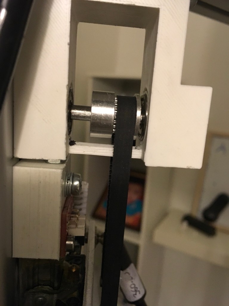
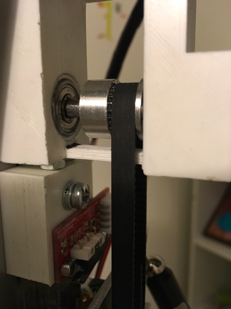
Here is the link for the idler mount. I had 625zz bearing on both sides of the idler mount for the dowel pin. The shorter insert is on the tower side (you see the bearing in the above picture) and longer insert is on the opposite side(you don’t see the bearing). The idler mount is attached to the tower using a M6 Bolt and a spring loaded M6 T-nut inside the aluminium slot.
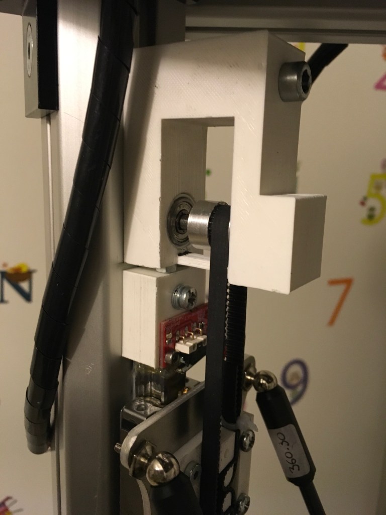
Initially, I did not tighten the M6 bolt completely because I wanted to slide up the idler mount to adjust the belt tension. Through trial and error, I found that if you place a M4 nut in between the endstop mount and idler mount printed part (look at the picture above), then I get the required tension. You have to use some brute force here.
The ideal engineering solution is to use a screw from the top in idler mount which could move it up the tower as you turn it. I was not so keen about this solution and left it as such.
Once you are sure that you have required tension, tighten the M6 bolt completely. How do you check the required tension? I refer you to Michael Hackney’s UltiBots D300VS build guide Step 44 – Preparing to tension the belts. For those, who don’t have patience. I summarize them.
- Install Easy Tension App
- Use Frequency meter option on the screen
- SLOWLY move all three carriages to the bottom of the printer so they touch the base
- Keep your phone microphone close to the belt at mid height
- Pluck the side of the belt that is not connected to the carriage
- A frequency of 38Hz is a good measure of tautness – Remember that this frequency is for 0.8-1.2 m long towers for GT2 belts.
- The frequency will vary for different length and linear mass of the belt
- Please consult appropriate physics formula, if your printer set up is different.
For extra tightening, I used printed belt tension-er with M3 bolt. Here is the stl file. Once you tighten the belts, check that the carriage is moving freely without any friction.
As we are done with the motion system, in the next post we will look into heated bed and bed leveling methods.
