
Delta – Extruders and Effectors – Introduction
In a series of posts starting from this one, I will talk about various extruders, effector setup (effector plate, cooling fan set up etc.) and my printing experience with them.
Eventually, over the course of one year, I tried four extruders, all of them in direct drive setup. I did not want to use bowden because of low print quality due to lag in response to retraction movements of extruder. The problem is aggravated with elastic filaments like ninjaflex. Here are those four extruders:
- Titan
- Nimble – Remote direct drive extruder
- Aluminium effector plate
- Smart effector
- Titan Aero
- Bondtech BMG extruder
Along with these extruders, I used
- E3D V6 heatsink,
- E3D regular heater block/Volcano heater block
- Regular nozzle/Hardened steel nozzle/Volcano nozzle and
- Zesty Tech’s water cooled heatsink
In most cases, I used E3D V6 heatsink and regular nozzle. In certain cases, I used volcano heater block especially with bondtech extruder. I used water cooled heatsink only with Nimble. I will go through each extruder setup and describe combinations of heatsink and nozzles I used with them. I used berd air cooling system only with nimble extruder. I will also discuss how these choices affected my effector plate and cooling fan mount designs.
Here is the list of experiments I did in tabular form:
| S.No. | Extruder | Heater Block | Nozzle | Heat Sink & Cooling | Part Cooling |
| 1. | Titan | Regular | Brass | E3DV6-Air | Fan |
| 2. | Nimble | Regular | Brass | E3DV6-Air | Fan |
| 3. | Nimble | Regular | Brass | E3DV6-Air | Smart Effector+Fan |
| 4. | Nimble | Regular | Brass | E3DV6-Air | Berd Air |
| 5. | Nimble | Regular | Brass | Kryo – Water | Fan |
| 6. | Titan Aero | Regular | Brass | E3DV6-Air | Fan |
| 7. | Titan Aero | Regular | Hardened Steel | E3DV6-Air | Fan |
| 8. | Bondtech | Regular | Brass | E3DV6-Air | Fan |
| 9. | Bondtech | Volcano | Brass | E3DV6-Air | Fan |
| 10. | Bondtech | Volcano | Hardened Steel | E3DV6-Air | Fan |
The extruder setup along with hotend, heatsink cooling fan, part-cooling fan and z-probe will be mounted to the effector plate. Our ultimate aim is to 3D print parts as accurate as possible with less chance for print failure. In delta printer, it is easy to make some build errors, which will result in effector tilt caused by moment. The tilt may displace the hotend nozzle and create imprecision. It also can have an effect on Z-probe, when the probe is offset from the hotend, for ex. like an IR sensor.
Two things have important effect on an effector stability:
- The geometry, as different geometries may induce higher or lower loads on arms and articulation, so higher or lower deformation. A geometry reducing the load will increase precision.
- The moment resistance induced by arm articulation,
The moment which will induce tilt will be created by :
- Inertia
- Load on the nozzle
- Friction in articulation, which may be significant for some types of articulations
If you look at the effector geometry below and read the wikipedia page, it says that the stability is directly proportional to the arm spacing and inversely proportional to ‘b’, the spacing between adjacent arm’s articulated ball joints. It shall be noted that wider arm space does not raise or decrease the moment and only help to fight play in articulation.
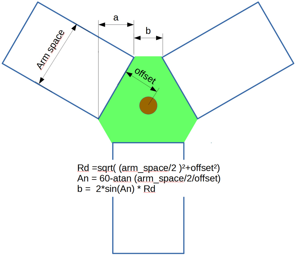
There are some practical limitations to increase the arm spacing, if you have large arm spacing, the carriages will be wide apart, which increases the warping tendency leading to worse stability results. To have a large arm spacing, we need a large effector plate, which reduces the effective printing area of delta printer. Arm spacing can be reduced to a bare minimum. In one of the delta robot implementations called spider bot, instead of 6 balls, there are only 3 balls, one each at the end of effector triangle (‘b’ = 0). The adjacent arms hinge on a single ball as shown below:

Anyways, implementing spiderbot might be theoretically a good idea but I did not want to spend too much effort on this aspect. You can use good mechanical practices listed below while building the printer to reduce the effector tilt.
- All the 6 arms of the delta printer, should be of same length – measured between bearing centres/magenetic ball centres. The variation should be less than +-0.1 mm . I use Haydn’s magnetic arms which vary little in length, in fact less than +-0.05mm
- Carriages which move along the tower should not be warped about z-axis. If they are warped, then the bearings in carriages are at different lengths compared to effector, which results in a moment, leading to effector tilt. I use aluminium effector plates, so only minimal warping.
- Spacing between arms at the effector plate and spacing between arms at the carriage should be the same, if at all there is any variation, it should be less than +-0.1 mm. I measure them to make sure they are same, if not you have to adjust them (print a new effector).
When I was reading through reprap and google delta forums, I gathered these tips from users to reduce the tilt:
- Arm spacing is roughly 1/6th to 1/5th of arm distance.
- Keep the plane of the nozzle is as close as to the effector plane.
- Increase the stiffness of effector plate – Use PCB sheets or aluminium plate or printed effector with 100% infill.
I hope ll these guidelines will help someone to understand effector tilt and design a better effector for precise printing. In the coming posts, I will talk about these four extruders and experiments associated with it.
