
Delta – Extruder – Nimble – Part 1
In this post, I will describe my experiences with the very first version of Nimble, I will also give a brief description about this remote direct drive setup. I did the most number of experiments with this extruder setup.
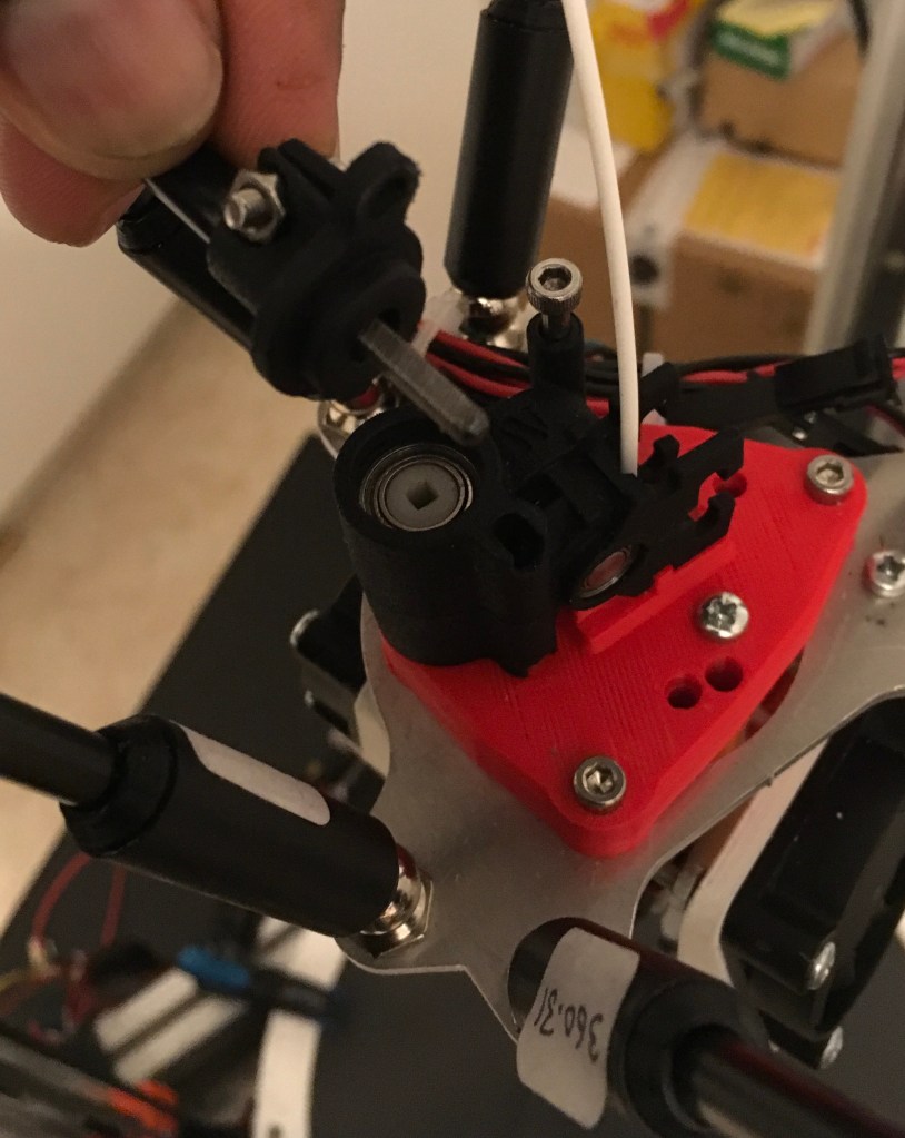
Nimble is a remote direct drive extruder. In the image below, you can see a thick black cable coming from the stepper motor at the bottom right of the picture. The stepper motor drives the extruder remotely.

In conventional direct drive extruders, the motors sits right next to the extruders but the whole setup becomes heavy. It creates a lot of inertia and limits your printing speed. The remote direct drive extruders like Nimble get rid of the extra mass of motor from the effector by remotely placing the stepper motor in printer body.
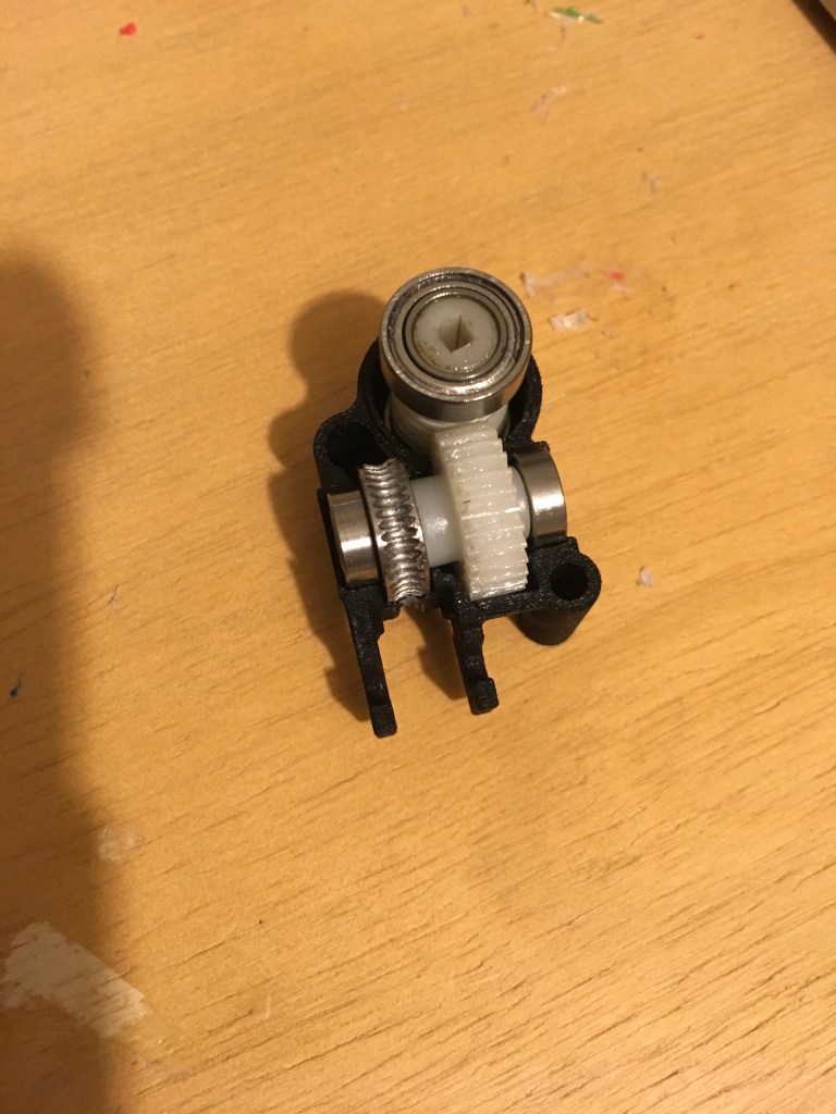
The stepper motor drives the extruder gears via a flexible steel shaft (shown in the picture below), which is inserted into the slot, which drives the worm screw made of acetal. The worm screw drives the worm gear, the reduction ratio is 20:1. The worm gear is attached with a steel hobb, which pushes the filament inside.
Since the nimble is a lightweight system, we don’t need a big effector to house the stepper motor and extruder but stiff and smaller footprint.
I was wondering about lasercut aluminium as an effector plate with some printed adaptors for nimble. I got the dxf file for aluminium plate from DJDemon’s thingiverse page. Here is the picture:

The printed carriage was designed by Lykle Schepers of Nimble. Here is the link to the stl file. You can also look at this thingiverse page for various adapters. He was very supportive when setting up the nimble and provided me with necessary adapter designs.

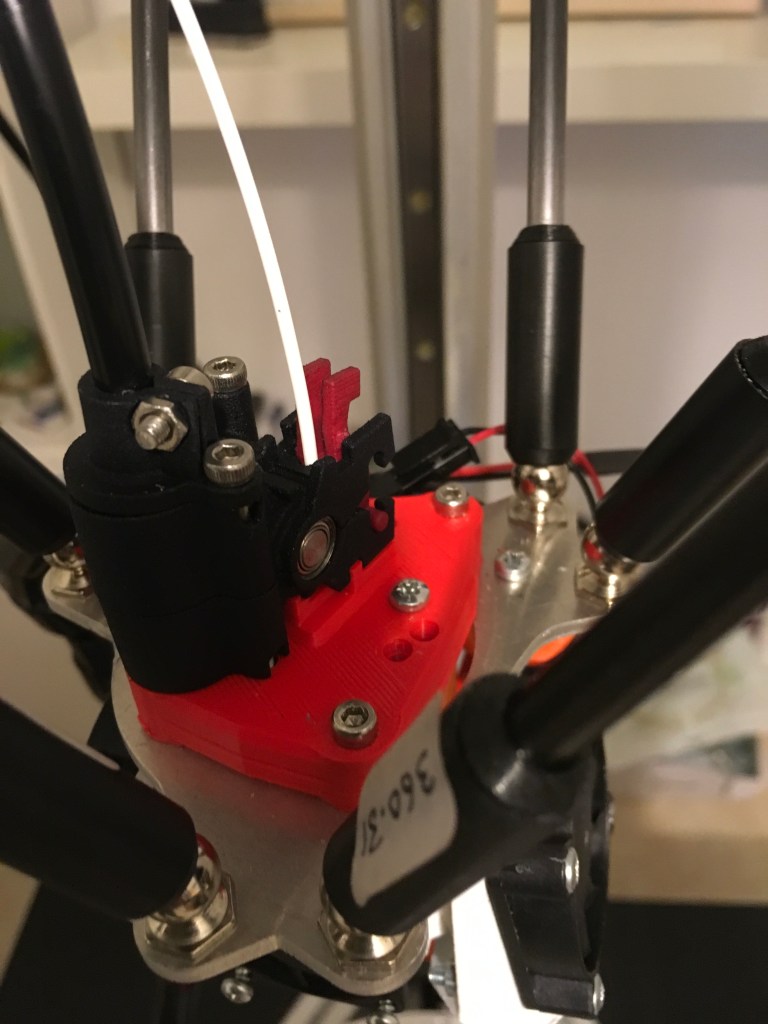
Here is the laser cut aluminium effector plate with the printed adapter mounted on printer:
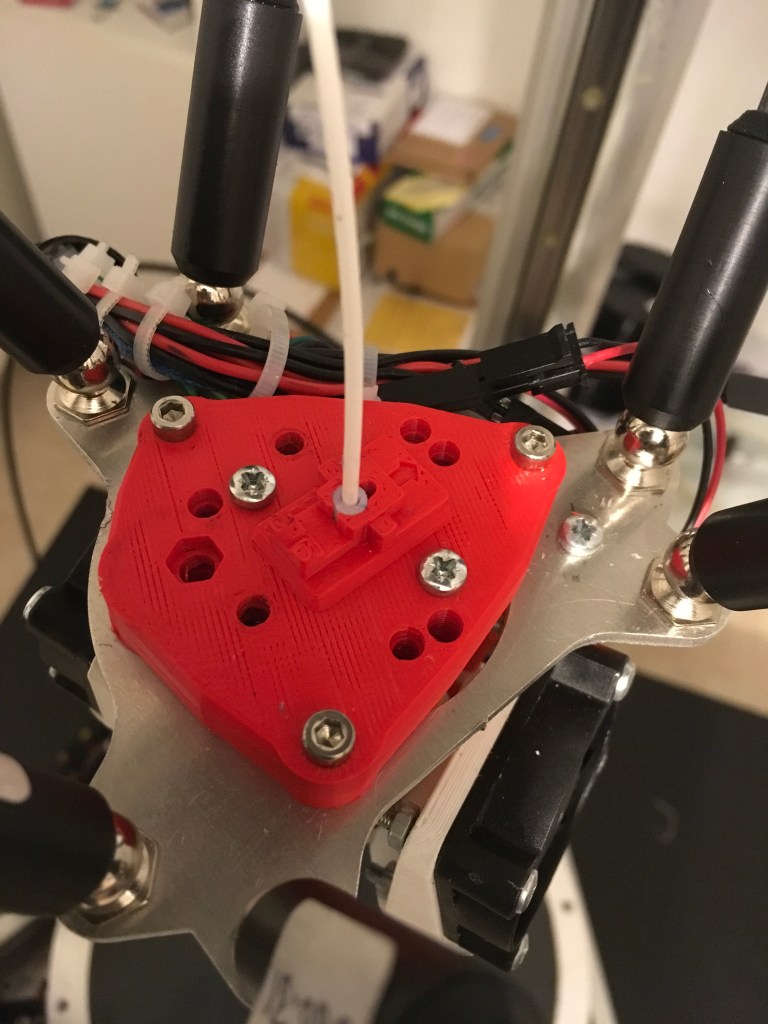
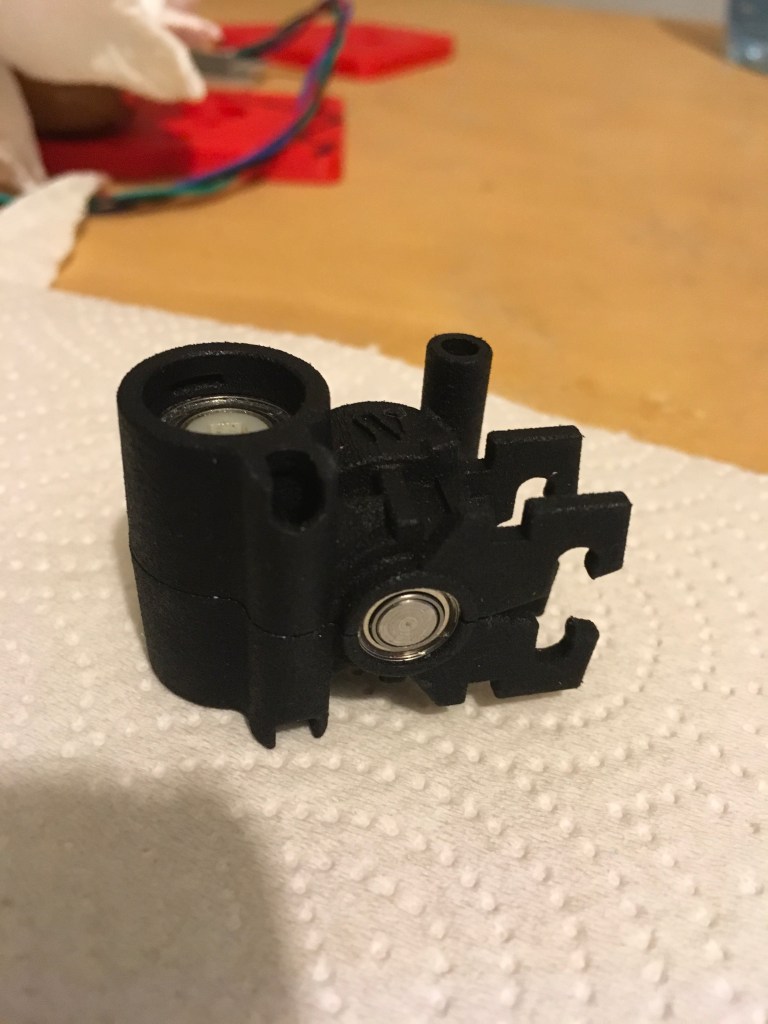
Now the Nimble is mounted with filament but without the breech lever. For nimble assembly and mounting instructions please refer to its documentation.
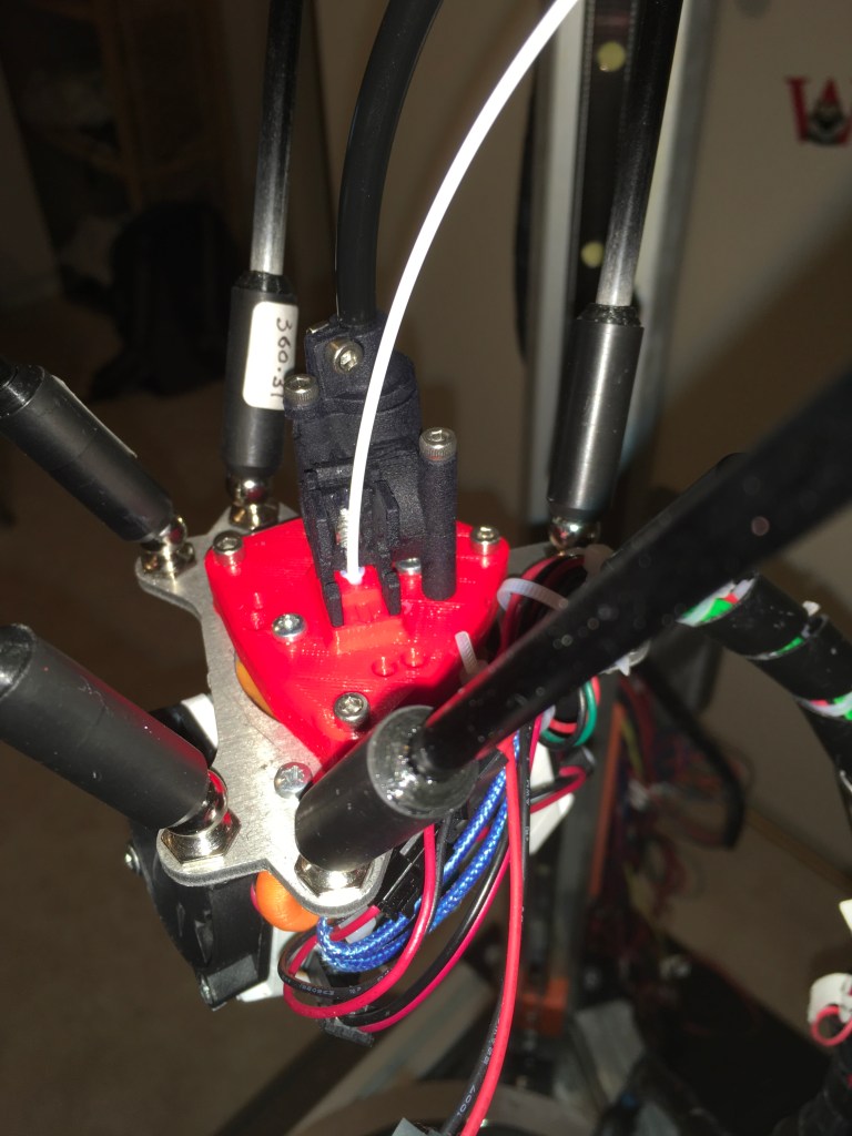
Finally, the breech lever (red ears next to white filament) along with a bearing presses the filament against hobbed gear, creating some grip, which helps to push the filament into the hotend.
One of my minor complaints with nimble is the lack of adjust ability of filament grip. The breech lever just sets the pressure, there is no way to manually increase or reduce the grip. In other extruders, you have a screw which increases or decreases the bearing pressure against the hobbed gear.
That said, in nimble, I rarely found the need to adjust the pressure, so the non-adjustable nature of breech lever was not a major issue for me.
Now coming to the cooling fan type, I used DJDemon’s 30mm cooling fan solution – Slimline Compact dual fan. It was also the time precision piezo’s version 1 sensor was out, so I thought I will try.
Nimble was the first extruder I tried piezo resistive sensor. In this experiment, I used Nimble + piezo sensor + aluminium effector + printed mount + E3DV6 heat sink+ dual 30mm fans. You can see the set up in the below pictures:


The precision piezo was fantastic, it was so reliable and bang on during auto calibration, I got perfect first layers every time. You can see a sample in the letters underneath the famous benchy part.
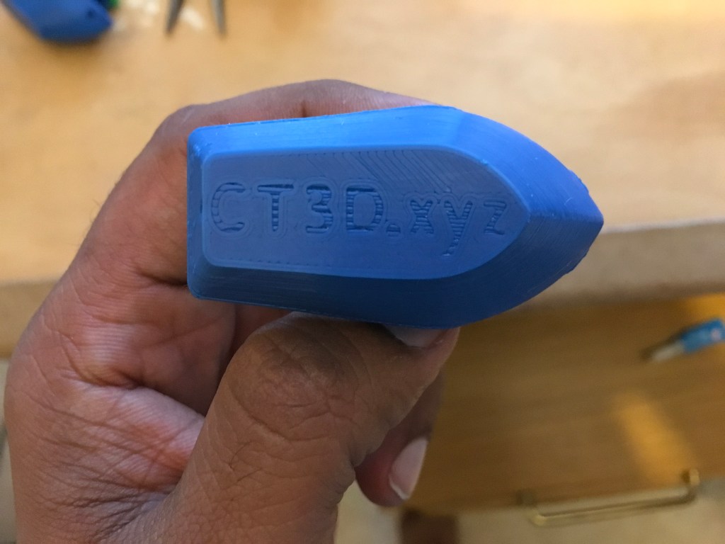
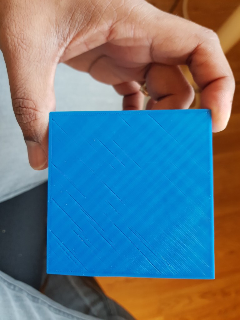
Here are some of the example parts I printed with this setup:

After printing some initial parts, I started noticing some irregular lines. You can notice that in the Idol of Ganesha (Hindu God).
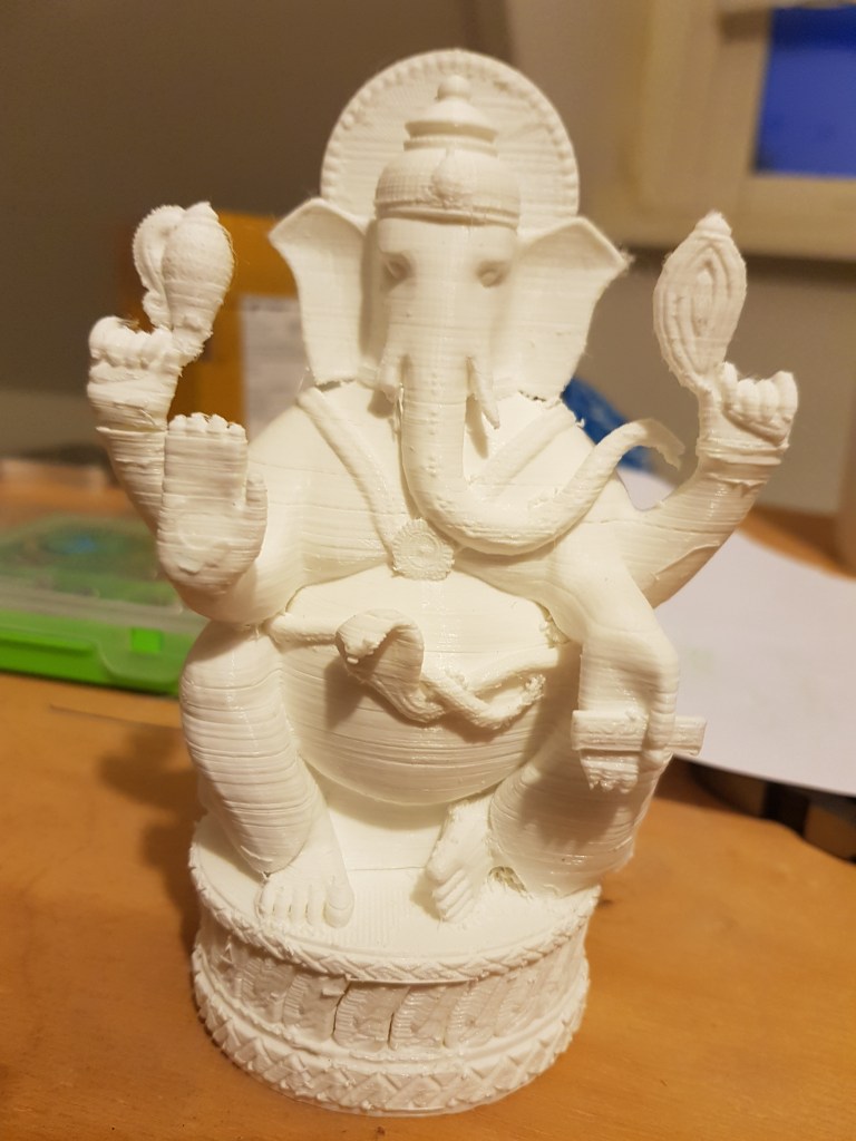
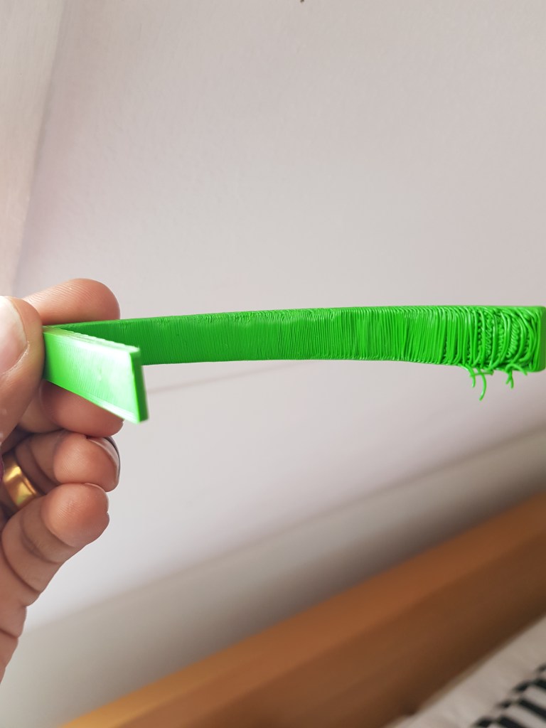
In subsequent printing, the print quality got worse. There was an intermittent feeding issue of filament, which makes empty passes (without filament extrusion) in certain parts of the layer.

Thankfully, Lykle Schepers helped me by scheduling a Skype call and looking at my setup to make sure it was a Nimble issue. Eventually we came to a conclusion that it might be due to a faulty nimble. Lykle was also designing Nimble V1.1, so he graciously sent me a new model. I was really impressed with his attitude. He was fantastic with customer service. He did not just sell his product and reply my email with some suggestions or answer only in the forum. He personally took great interest in my set up and helped troubleshoot. Even after getting V1.1, I ran into the same set of problems. Lykle encouraged me to be persistent.
Eventually, over the course of our communication, we came to a conclusion that the worm screw might be slightly over-sized, so he suggested me to reduce the diameter. I attached the worm screw to a hand drill. Now, grind down the diameter by pressing the file uniformly on the crests of the worm screw. Since, the worm screw is attached to a rotating hand-drill, we can maintain the concentricity or reduce the eccentricity after filing down the gear.
Another tip that improved the print quality vastly was this secret ingredient – RC car diff gear lube oil – Silicone oil of viscosity 10,000 Cst. Take one or two drops of this oil and apply on both worm screw and worm gear. Allow the worm gear set up to lubricate by just running the extruder without filament.

I started getting better prints and this issue vanished completely after the above two fixes. During the same time, when I was disassembling the effector, I damaged the piezo wires, so I had to switch to FSR z-probe. I was thinking of changing from 30mm fan duct to 40 mm only because of noise. If I change the fan duct, I have to change the effector design. I had a simple trianglular printed mount that bolts to the holes in aluminium plate. Once again, Lykle designed the printed mount for me. Here is the stl file he provided. Here is the new effector with 40mm fan mounts designed for Titan direct drive.

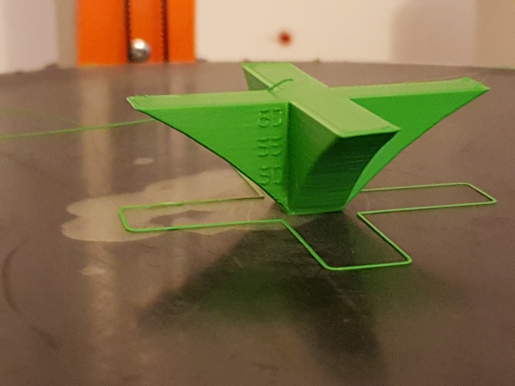
Here is a video of the mentioned mount printing a lattice cube torture test.

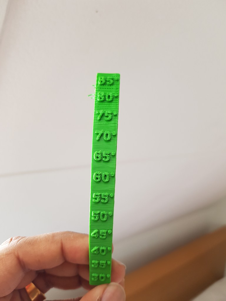
The part came out good in retraction testing. I tested cooling fan capabilities also, overall I was able to get the nimble working nicely. Here are some gallery pictures.

I will talk about the other experiments with nimble in the next series of posts.
